Operating Principle of the Pilot Valve
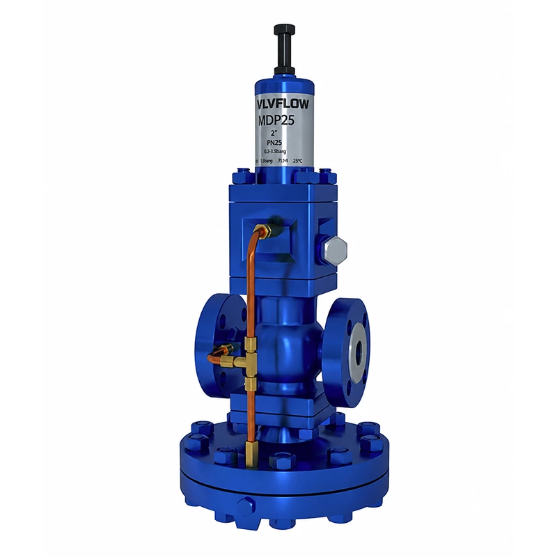
The modular design allows any type of pilot valve to be connected to the main valve, enhancing flexibility in pressure reduction operations.
In the initial state, the main valve is closed, while the pilot valve is held open by spring force. Steam flows through the pilot valve and the pressure control line into the main valve’s diaphragm chamber. Simultaneously, a portion of the steam passes through a control orifice toward the downstream side. This increases the control pressure exerted on the main valve diaphragm, causing the main valve to open.
As steam flows through the main valve, the downstream pressure rises. This pressure is fed back via a downstream pressure-sensing line to the underside of the pilot valve diaphragm (a downstream pressure-sensing line must be installed to ensure stable downstream pressure). This feedback force causes the pilot valve to gradually throttle and close, reaching an equilibrium with the spring force acting on the top of the diaphragm. This process regulates the pressure within the main valve’s diaphragm chamber, controlling the opening of the main valve to deliver the appropriate amount of steam and maintain a stable downstream pressure. If the downstream pressure rises, the feedback pressure increases, causing the pilot valve to close; the pressure in the main diaphragm chamber is then released through the control orifice, allowing the main valve to close tightly.
Any changes in downstream load or fluctuations in pressure are fed back to the underside of the pilot valve diaphragm, which in turn adjusts the opening of the main valve to ensure the downstream pressure remains precise and stable. This feedback force causes the pilot valve to gradually throttle and close, reaching an equilibrium with the spring force acting on the top of the diaphragm. This process regulates the pressure within the main valve’s diaphragm chamber, controlling the opening of the main valve to deliver the appropriate amount of steam and maintain a stable downstream pressure. If the downstream pressure rises, the feedback pressure increases, causing the pilot valve to close; the pressure in the main diaphragm chamber is then released through the control orifice, allowing the main valve to close tightly.
| Category |
Parameter |
Specification |
| General Specifications |
Material |
Ductile Iron |
| General Specifications |
Nominal Size |
1/2"–6" |
| General Specifications |
Threaded Connection |
BSP, 1/2"–2" |
| General Specifications |
PN16 Flanged Connection |
DN25–DN150 |
| General Specifications |
PN25 Flanged Connection |
DN25–DN150 |
| General Specifications |
Maximum Operating Pressure (PMO) |
21 bar |
| General Specifications |
Flow Rate |
39–58,977 kg/h |
| Design Features |
Design |
Pilot-operated design |
| Design Features |
Seat Leakage |
Low-leakage metal seat; Class VI leakage optional |
| Design Features |
Differential Pressure |
Suitable for high differential pressures |
| Design Features |
Application |
Optional configuration for stringent leakage requirements |
| Design Range |
Seat Diameter |
32–200 mm |
| Design Range |
Pressure Rating |
PN16–PN63 |
| Design Range |
Temperature Range |
−196°C to +425°C |
| Design Range |
End Connections |
Flanged or Welded |
| Design Range |
Actuator Air Supply Pressure |
1.4 bar, 2.4 bar or 4 bar (optional) |
| Environmental Requirements |
Ingress Protection |
High level of sealing and ingress protection |
| Environmental Requirements |
Corrosion Protection |
High-quality anti-corrosion treatment |
| Environmental Requirements |
Operating Environment |
Suitable for a wide range of environmental conditions |
| Accessories |
Positioner |
Electro-pneumatic valve positioner |
| Accessories |
Air Supply Treatment |
Air filter regulator |
| Accessories |
Directional Control |
Directional solenoid valve |
| Accessories |
Position Monitoring |
Valve position feedback |
| Accessories |
Optional Accessories |
Volume booster and air lock-up valve |